|
Modular 6502 SBC with
emulated CPU |
|
|
|
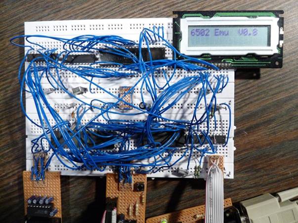
My test setup –
bottom: ATMega16 with a 32k SRAM, 64k I²C EEPROM, top: 2*74HC573, 6532, LCD …and
yes, it works on a breadboard. |
Overview
The minimum system
consists of an ATMega32, an SRAM IC and some components to provide a clock
source and an RS232 interface. Non volatile program storage can be added in
an I²C EEPROM connected through a bilateral switch. Examples in the source
code showcase, how parallel IO can be added from simple latches to 65xx IO
ICs. The emulation
provides: o some of the ATMega’s internal IO
capabilities RS232 I²C/TWI SPI Timers Interrupt pins as IRQ and NMI
inputs o proper sequencing of tags for parallel IO
devices glue logic replaced by emulation
IO modules and simple registers o a debugger & monitor outside of the
emulated CPUs code space alter and display registers and
memory program control – start, stop,
single step & breakpoint trap undefined opcodes or STP
instruction o loading or booting code images to
RAM from RS232 (monitor console) serial I²C or SPI EEPROM The achievable 6502
equivalent clock speed is approximately 2 MHz at 16 MHz ATMega clock. In order to combine
the required IO blocks for your own SBC design, some AVR assembler knowledge
is required. The emulator source code contains extensive comments about
configurable items and the usage of emulated registers in the IO page. Project status, planned additions
Previous: Version 0.8 is the initial
release. It has passed all tests of the emulated opcodes, IO loopback to I²C
EEPROM, 74HC573 latches, a 6532 RIOT and a HD44780 compatible LCD. Version 0.81 – Added binary
load/save/autoload support for applications. Added optional software flow
control to RS232 receive buffer and tested with PuTTY and Tera Term. Modified
EhBASIC for use with the emulator. Condensed all configurable items into a
single include file. Added timer 1 access. Tested and improved interrupts. Version 0.82 – Added optional
65C02 opcodes emulation. Version 0.83 – Added breakpoint
capability. Added SPI support. Added virtual but interruptible DMA for both I²C
& SPI. Added documentation about customizing the AVR source and using the
IO‑registers. Updated hardware
and debugger documentation. Merged all documentation into a single document. Major update: the configuration include must be replaced
with version 0.83. Version 0.83a – Modified atomic
mode (irq_dis_real defined) to accept single step and NMI. Version 0.83b – Bug fixes only.
The last version fitting the ATMEGA16
(low-flash branch on GitHub): Version 0.83c – Fixed DMA load
program corrupted message. Current (master branch on GitHub): Version 0.84 – Improved ADC/SBC
binary/decimal switch (thanks to Peter!) Added a switch to force hardware compatible results on invalid BCD. Added MMU support to switch banks, copy or swap pages between banks. Added SPI/I2C DMA support to read, write, save or load banks. Added IO subprocessor support. Add: o Add SD-card support o enable a special SD-card file to
replace the serial EEPROM Documentation & Downloads
https://github.com/Klaus2m5/AVR_emulated_6502_4SBC Links
6502.org: The 6502 Microprocessor Resource – lots of information and
an active forum Atmel AVR Microcontrollers – documentation and IDE for the
ATMega16 & ATMega32 Frank's Cross Assemblers – AS65, the assembler that I use PSPad code editor – set up as a frontend to AS65 PuTTY – although it does much more, I use it as a
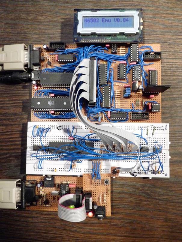
serial terminal emulation Tera Term – can be used as an alternative Testing the IO subprocessor on a breadboard
The mainboard has
512k of RAM with MMU, connectors for ISP, main bus, SPI and I²C. IO selects 10-13 are used
for on board units while IO selects 14-17 are available on the main bus
extension connector. The jumpers to the left of the SD card are used to
configure the inactive state of IO select 14-17. In addition to carrying the data byte and
the low address byte the main bus extension can be configured with the
jumpers at the bottom to carry either the high address byte, the IO select 2
byte (phi2 not available) or the IO select 3 byte (NMI not available). The
SPI section has 3.3V voltage conversion to support an SD card. The jumpers to
configure the 4 external slave select inactive states are at the top of the
board. The I²C section has a 64k EEPROM.
The new IO
subprocessor is on the breadboard together with 2 serial EEPROMs to test the
SPI and I²C hardware. An AVR910 programmer at the bottom is used to update
the firmware of the subprocessor. |